SafeEd System and User Guide
About the tool
In the past few years the number of safety
critical systems has grown, the question is how do we know
if they are safely-made and secure, any system that
presents a certain level of risks must prove that its
behavior should be trusted. Nowadays software safety
assurance is often demonstrated by compliance with
national or international safety standards. The assurance
cases are used to decide if the system is safe and secure
solely from the provided evidence. Their usage has grown
in the last years and in certain domains, like the nuclear
field, it is mandatory to build a safety case. This proves
that, currently, assurance cases are the answer to our
question. Assurance cases have evolved from the concept of
safety cases and they contain claims supported by the
evidence obtained during development and testing of the
system. It is very important to build well-structured and
coherent safety cases because wrong construction and
reasoning in safety arguments can undermine a systems
safety claims and lead to failures of the system. Over the
last years, many documents have appeared about how to
describe and graphically structure an assurance case. One
of these documents is the Goal Structuring Notation, also
known as GSN. The Goal Structuring Notation is an
argumentation notation used to structure and graphically
represent a safety argument. Even though we have a solid
standard for representing safety cases, it doesn’t reduce
the risk of building incomplete and bad-structured
assurance cases because of bad assessment of the safety
case, i.e the number of claims could be very high and
therefore will be hard to follow by the safety engineer. A
solution to this problem is to develop a tool that
facilitates the construction and assessment of safety
cases.
The main feature of the tool is to translate the GSN graphical notation into description logic in order check the GSN model for consistency. Hence, the GSN model for a safety critical application can be specified both in graphical notation and in description logic. The advantage is that the specific reasoning services of description logic are enacted to verify the compliance of the case with the GSN standard and also to signal possible argumentation flaws
The main feature of the tool is to translate the GSN graphical notation into description logic in order check the GSN model for consistency. Hence, the GSN model for a safety critical application can be specified both in graphical notation and in description logic. The advantage is that the specific reasoning services of description logic are enacted to verify the compliance of the case with the GSN standard and also to signal possible argumentation flaws
Installation Guide
In this section the main installation and
configuration issues for this system are addresed. For
using the tool, the user needs to have installed on the PC
the following tools:
- Eclipse Distribution with Epsilon(latest and updated version)
- Racer
reasoner
- SafeEd plugin (the plugin can be downloaded here)
- Open the wizard and select from Eclipse top menu Install/Update->Availbale Software Sites
- Click the Add.. button
- If the sofware site is in your local file system click Local.. to specify tyhe directory location of the file.
- If the software site is in your local file but packaged as a jar or zip, click Archive... to specify the name of the file.
- Select Add Site...
- Select all checkboxes and Click next
- Accept Sofware license and click Finish.
- A. Groza, N. Marc - Consistency Checking of Safety Arguments in the Goal Structuring Notation Standard, IEEE 10th International Conference on Intelligent Computer Communication and Processing (ICCP2014), Cluj-Napoca, Romania, 4-6 September 2014, pp 59-66 (pdf) (bib)
- A. Groza, l. A. Letia, A. Goron and S. Zaporojan - A formal approach for identifying assurance deficits in unmanned aerial vehicle software, In Proceedings of 23 International Conference on Systems Engineering, Las Vegas, USA, Ed. H. Selvaraj, D. Zydek, G. Chmaj, Advances in Intelligent Systems & Computing Series, Vol 1089, ISBN 978-3-319-08421-3, Springer (pdf) (bib)
- Nicoleta Marc, JUSTIFYING
SOFTWARE SYSTEMS SAFETY USING ARGUMENTS ,
Bachelor thesis, Computer Science Department,
Technical University of Cluj-Napoca
User's manual
Before using the tool the user has to
start the Racer engine.
Adrian.Groza [at] cs.utcluj.ro
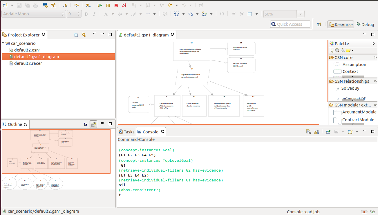
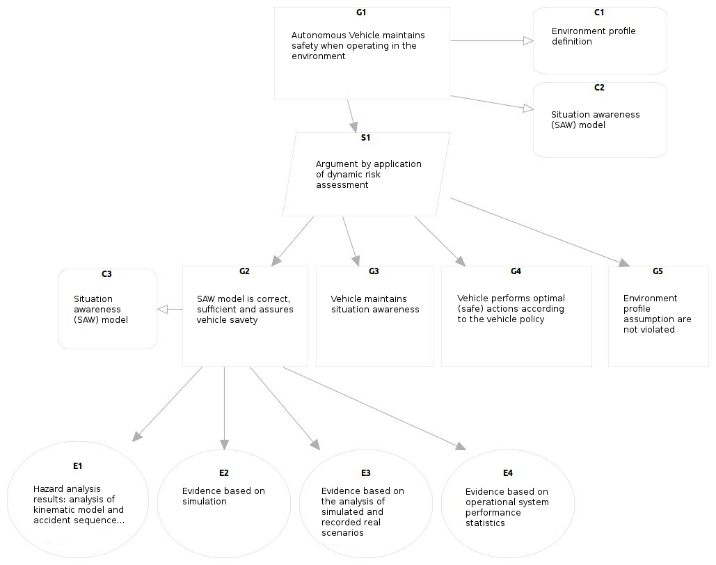
Creating a project and
add diagram to it
This action will add a new
project to the workspace and the diagram in it. A
safety project consists of several assurance cases,
developed either as a graphical diagram (files with
gsn extension) or as an abox in description logic
(files with racer extension). In case of need the
system automatically translated between these two
input formats. For a selected diagram file the user
can transform into abox, validate the diagram and
generate reports. The main window (top-cencer)
depicts the active gsn diagram. The elements of the
GSN standard are represented as follows: goals with
rectangular, strategies with paralelograms, evidence
and solutions are represented by circle, assumptions
and justifications with ellipse, context by a
rectangular with rounded corners, the supportedBy
relation is an arrow with the head filled, while the
inContextOf is represented by an arrow with empty
head.The title and description of a node can be
entered by clicking on the node in the head part for
the title, and in the field with the placeholder
`description`. The built-in actions performed on the
diagram are visible when clicking right on the
diagram or model file. Steps:
- select File->New->Projectselect General-> Project
- select next, give a name to your project and click finish
- press right click in the created project and select New->Other
- in the pop up wizard type GSN and select GSN1 diagram type
Figure 1
Transform diagram into
A-box
The output of this action
will be a new file having the same name as the
diagram and the extension .racer located in the same
project folder as the diagram, an example can be
seen in figure 2. The file is not loaded yet into
Racer engine.

- select diagram file, press right click on the file
- select Ontology->Transform A-Box
Figure 2
Load an diagram into
engine
In this action the user can
add the A-box to the T-box in the Racer and will set
it as main A-box. It should be selected only if the
racer file has been generated.
- select diagram file, press right click on the file
- select Ontology->Load A-Box
Figure 3
Validation & Report
generation
Three types of reports cand
be generated: validation report, to-do report and
documentation. When validating a diagram,the tool
writes the results of the validation in validate.log
file, this file will also contain the results of the
previous validations of this or other files. An
example of this report is shown in figure 4.
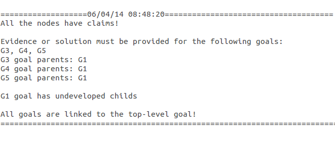
Figure 4
Querying the diagram
In the command line,
specific queries for interrogating ontologies can be
added and the reasoning engine will return the
results for each query. The syntax of the queries
corresponds to the RacerPro tool. Example of queries
usage: retrieving all the goals in the diagram,
identifying the top level goal, listing all pieces
of evidence supporting a goal, checking the
consistency of a diagram with respect to the GSN
standard encoded as axioms in description logic. The
user can query a diagram by following the next
steps:
- if the command-console is not visible then add it in the view by selecting from toolbar window->perspective->other the "Command Console"
- Write "start" and press enter to activate the console
- select Ontology->Load Abox (to be sure that the diagram si loaded)
- write the query and press enter
Contact
nicoleta.catalina.marc [at] gmail.com Adrian.Groza [at] cs.utcluj.ro